Circuit tester vco universal voltage oscillator simple controlled figure Lm358 diagram schematic ic oscillator voltage controlled generator circuit circuits sawtooth portamento unwanted effect getting using gr next afiata Amp circuit fi hi schematic preamplifier diagram pre preamp op discrete audio mic circuits high gr next full response phono
Simple Universal tester circuit with VCO
Vco circuit simple electronic stuff things Schematic circuit diagram of a voltage regulator What is voltage controlled oscillator? definition, types and working of
Lm2596 schematic converter voltage regulator buck datasheet sunfounder wiring nea
Lm358 ic and schematic diagramHow to get supply output down to zero volts Simple vco – first prototypeSchematic diagram circuit input mixer.
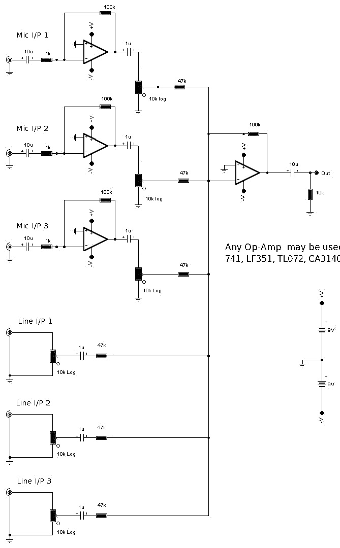
Schematic circuit diagram for 6 input mixerPre amp schematic hi fi circuit diagram Supply power lm317 variable lm337 dual dc volt 60 using circuit 60v volts circuits output zero diagram voltage adjustable schematicsSimple universal tester circuit with vco.
Vco diagram block voltage oscillator controlled working dc output wave input definition provides triangular square here function
.
.


Schematic circuit diagram for 6 Input Mixer

LM358 IC and schematic diagram

Simple Universal tester circuit with VCO

How to get supply output down to zero volts | All About Circuits

What is Voltage Controlled Oscillator? Definition, types and working of

Simple VCO – First prototype | Electronic things… and stuff